Molding high quality parts is dependent on many factors, including skillful part and mold design, an understanding of polymer material behavior, and an optimized process. The three common nozzle tip designs found in the injection molding industry are general purpose, reverse taper, and free flow. Nozzle tip design and size will impact mold filling, process behavior, and stability.
If the orifice is too small, the required injection pressure to inject material through the nozzle may be high. This would reduce the available machine pressure needed to fill and pack the mold.
Also, keep in mind that the nozzle tip is in contact with the cold mold, so it will get cold quickly. A small nozzle orifice could freeze the polymer too soon which would impact the ability to properly pack the part. In this scenario the cold plug could also be injected into the next cycle, potentially causing process and part quality-related surface defects.
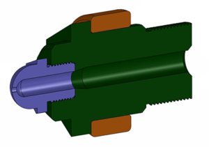 The general-purpose nozzle tip design has the potential for a dead spot as highlighted on the screen. When polymer material is injected, the main flow channel is directed to the small orifice. Because polymer flows along the path of least resistance, this area is no longer a preferred flow path, meaning that polymer can remain stuck in there for longer. When the material sits in this dead area, it is exposed to heat which can result in altered material properties. Overheated material that is injected can create part surface defects.
When materials or colors are changed, the general-purpose nozzle tip must be thoroughly cleaned prior to setting up the new molding process.
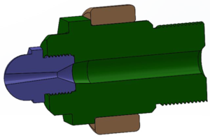 The reverse taper nozzle tip has a wider orifice diameter which won’t freeze as quickly at the intersection to the mold sprue bushing as the general-purpose design with the significantly smaller orifice.
When the mold opens the partially frozen reversed taper gets pulled out of the nozzle tip. The separation point is at the smallest diameter portion, as shown on the screen. Because the thinnest section is located further inside the tip, the temperature is higher, so the material may still be molten.
Processing tools with a reversed taper nozzle tip can be challenging because the tool and process functionality is dependent on the temperature behavior inside the nozzle tip.
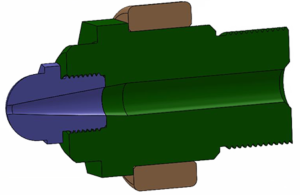 The free-flow tip’s diameter gradually decreases and leads to a small orifice land. The gradual reduction eliminates the dead spots that were apparent in the general-purpose design.
When the nozzle orifice is machined to accommodate the sprue bushing, the gate land becomes automatically longer. Although the larger orifice size could allow material to “drool” out of the tip, the longer land would prevent this outcome.
Different nozzle tip designs and sizes influence mold filling, process behavior, and stability. By understanding the advantages and disadvantages of each tip design and seeing how their use will affect temperature and pressure inside a mold during the filling and packing phases, a mold designer has the tools for designing an optimized mold.
Remember, molding high quality parts is dependent on many factors, including skillful part and mold design, an understanding of polymer material behavior, and an optimized process.
_____________________________________________________________________________________________________________________
A full lesson on Nozzle Tip Designs and Injection pressure is available to our subscribers. Learn more and subscribe to Kruse Training today!